L4#1 configuration
>> Main# /c/dump
script start "Alteon 180e" 4 /**** DO NOT EDIT THIS LINE!
/* Configuration dump taken 17:41:11 Tue Jan 3, 2012
/* Version 10.0.28, Base MAC address 00:60:cf:42:d4:10
/c/port 1
pvid 192
/c/port 2
pvid 20
/c/port 3
pvid 10
/c/port 5
pvid 10
/c/port 8
tag ena
pvid 100
/c/vlan 1
def 4 6 7 9
/c/vlan 10
ena
name "VLAN 10"
def 3 5 8
/c/vlan 20
ena
name "VLAN 20"
def 2 8
/c/vlan 100
ena
name "VLAN 100"
def 8
/c/vlan 192
ena
name "VLAN 192"
def 1 8
/c/stp 1/off
/c/stp 1/clear
/c/stp 1/add 1 10 20 100 192
/c/trunk 1
ena
add 8
/c/ip/if 1
ena
addr 192.168.1.52
vlan 192
/c/ip/if 2
ena
addr 20.20.20.2
mask 255.255.255.0
broad 20.20.20.255
vlan 20
/c/ip/if 3
ena
addr 10.10.10.2
mask 255.255.255.0
broad 10.10.10.255
vlan 10
/c/ip/if 8
ena
addr 1.1.1.2
mask 255.255.255.0
broad 1.1.1.255
vlan 100
/c/ip/gw 1
ena
addr 192.168.1.60
/c/vrrp/on
/c/vrrp/hotstan enabled
/c/vrrp/vr 10
ena
vrid 10
if 3
addr 10.10.10.1
adver 2
share dis
track
ports e
/c/vrrp/vr 20
ena
vrid 20
if 2
addr 20.20.20.1
adver 2
share dis
track
ports e
/c/vrrp/vr 100
ena
vrid 100
if 8
addr 1.1.1.1
adver 2
share dis
/c/vrrp/vr 192
ena
vrid 192
if 1
addr 192.168.1.51
adver 2
share dis
track
ports e
/c/vrrp/group
ena
vrid 1
if 1
prio 101
share dis
track
vrs dis
ifs dis
ports ena
l4pts dis
reals dis
hsrp dis
hsrv dis
/c/slb
on
/c/slb/adv
direct ena
/c/slb/sync
state e
/c/slb/real 1
ena
rip 10.10.10.12
/c/slb/real 2
ena
rip 10.10.10.13
/c/slb/group 1
metric hash
health http
add 1
add 2
/c/slb/group 2
add 1
add 2
/c/slb/port 1
client ena
hotstan ena
/c/slb/port 2
client ena
hotstan ena
/c/slb/port 3
client ena
server ena
hotstan ena
/c/slb/port 5
server ena
hotstan ena
/c/slb/port 8
client ena
intersw ena
/c/slb/virt 1
ena
vip 10.10.10.10
/c/slb/virt 1/service http
group 1
/c/slb/virt 2
ena
vip 10.10.10.11
/c/slb/virt 2/service ftp
group 2
ftpp ena
/c/slb/virt 2/service ftp-data
group 2
/
script end /**** DO NOT EDIT THIS LINE!
L4#2 configuration
>> Configuration# /c/dump
script start "Alteon AD3" 4 /**** DO NOT EDIT THIS LINE!
/* Configuration dump taken 17:46:01 Tue Jan 3, 2012
/* Version 10.0.28, Base MAC address 00:60:cf:49:ea:d0
/c/sys
tnet ena
/c/port 1
pvid 192
/c/port 2
pvid 20
/c/port 3
pvid 10
/c/port 5
pvid 10
/c/port 8
tag ena
pvid 100
/c/vlan 1
def 4 6 7 9
/c/vlan 10
ena
name "VLAN 10"
def 3 5 8
/c/vlan 20
ena
name "VLAN 20"
def 2 8
/c/vlan 100
ena
name "VLAN 100"
def 8
/c/vlan 192
ena
name "VLAN 192"
def 1 8
/c/stp 1/off
/c/stp 1/clear
/c/stp 1/add 1 10 20 100 192
/c/trunk 1
ena
add 8
/c/ip/if 1
ena
addr 192.168.1.53
vlan 192
/c/ip/if 2
ena
addr 20.20.20.3
mask 255.255.255.0
broad 20.20.20.255
vlan 20
/c/ip/if 3
ena
addr 10.10.10.3
mask 255.255.255.0
broad 10.10.10.255
vlan 10
/c/ip/if 8
ena
addr 1.1.1.3
mask 255.255.255.0
broad 1.1.1.255
vlan 100
/c/ip/gw 1
ena
addr 192.168.1.60
/c/vrrp/on
/c/vrrp/hotstan enabled
/c/vrrp/vr 10
ena
vrid 10
if 3
prio 99
addr 10.10.10.1
adver 2
share dis
track
ports e
/c/vrrp/vr 20
ena
vrid 20
if 2
prio 99
addr 20.20.20.1
adver 2
share dis
track
ports e
/c/vrrp/vr 100
ena
vrid 100
if 8
prio 99
addr 1.1.1.1
adver 2
share dis
/c/vrrp/vr 192
ena
vrid 192
if 1
prio 99
addr 192.168.1.51
adver 2
share dis
track
ports e
/c/vrrp/group
ena
vrid 1
if 1
share dis
track
vrs dis
ifs dis
ports ena
l4pts dis
reals dis
hsrp dis
hsrv dis
/c/slb
on
/c/slb/adv
direct ena
/c/slb/sync
state e
/c/slb/real 1
ena
rip 10.10.10.12
/c/slb/real 2
ena
rip 10.10.10.13
/c/slb/group 1
metric hash
health http
add 1
add 2
/c/slb/group 2
metric hash
health ftp
add 1
add 2
/c/slb/port 1
client ena
hotstan ena
/c/slb/port 2
client ena
hotstan ena
/c/slb/port 3
server ena
rts ena
hotstan ena
/c/slb/port 4
rts ena
/c/slb/port 5
server ena
hotstan ena
/c/slb/port 8
client ena
intersw ena
/c/slb/virt 1
ena
vip 10.10.10.10
/c/slb/virt 1/service http
group 1
/c/slb/virt 2
ena
vip 10.10.10.11
/c/slb/virt 2/service ftp
group 2
ftpp ena
/c/slb/virt 2/service ftp-data
group 2
/
script end /**** DO NOT EDIT THIS LINE!
'업무이야기 > Network' 카테고리의 다른 글
| ServerIron의 SLB(Server Load Balancing) (0) | 2012.01.04 |
|---|---|
| Alteon L4 스위치 기본 설정방법 (0) | 2011.12.26 |
| Alteon L4 스위치 VRRP (0) | 2011.12.21 |
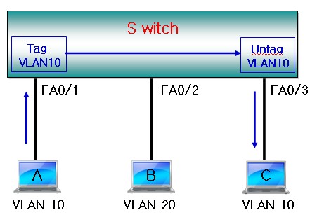
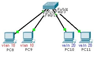
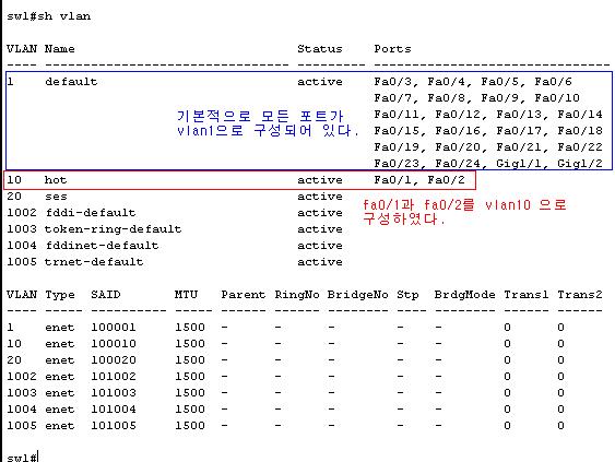
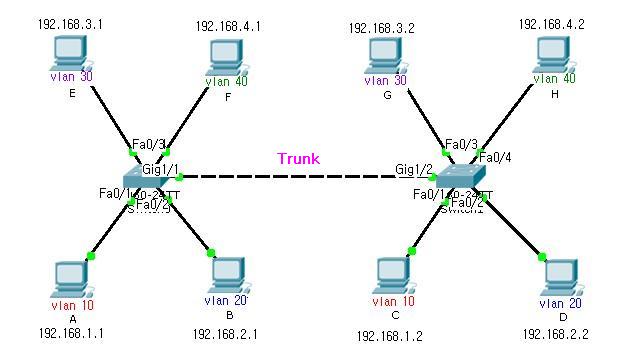
| VLAN 과 Trunk (0) | 2011.11.23 |
| Etherchannel Config 설명 (0) | 2011.11.23 |